Instrument Cluster Diagnostics and Repairs Theme 93

Instrument Cluster Diagnostics and Repairs

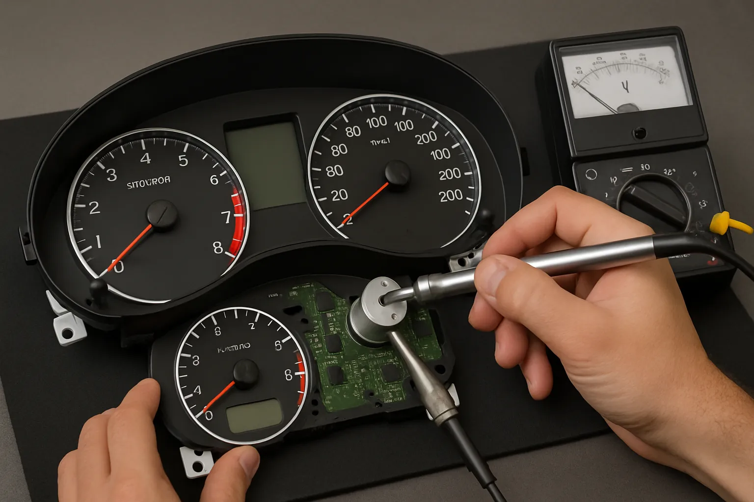
This theme shows you how to diagnose and repair common instrument cluster faults, including cracked solder joints, failed LCD screens, damaged electronic components, and when cloning a donor cluster becomes the most practical solution.

YOUR PROGRESS IN THIS COURSE
complete

Step 1: Read the text

Instrument clusters can fail due to cracked solder joints, damaged LCD screens, or defective electronic components.
Cracked solder joints often cause intermittent power loss, flickering displays, or gauges that stop working when the vehicle vibrates.
LCD faults may include missing pixels, dim backlight, distorted information, or a completely blank screen.
Internal component failures such as voltage regulators or drivers can lead to total cluster shutdown or communication errors.
When repair is not cost-effective, cloning data into a compatible donor cluster may be the most practical solution.

Step 2: Estimated Cost & Earnings

Used in: instrument cluster diagnostics, electronic repairs, soldering work, display and communication fault fixing

Typical service value: €100 – €300

Estimated time: 1 – 3 hours

Potential per day: €300 – €700

Step 3: Watch the video

Step 4: Common Mistakes to Avoid

These are the most common mistakes when diagnosing and repairing instrument clusters.

❌ Replacing the cluster without checking power, ground, and CAN signals

⚠️ Result: New cluster shows the same issue because the fault is in wiring or communication.

✅ Correct way: Always verify power supply, ground, and CAN communication before replacing the cluster.

❌ Poor soldering when repairing joints

⚠️ Result: Intermittent faults remain or new issues appear due to weak connections.

✅ Correct way: Use proper soldering technique with clean joints and correct temperature.

❌ Ignoring coding and immobilizer adaptation

⚠️ Result: Cluster works partially or vehicle will not start due to immobilizer mismatch.

✅ Correct way: Always perform coding and adaptation after replacing or cloning a cluster.

Step 5: Pass the test

What is the most common cause of intermittent instrument cluster operation when driving over bumps?

Step 7: Pass the test

Decide if the statement is True or False, then press Check answer.

Statement: Cracked solder joints in an instrument cluster can cause intermittent faults like flickering gauges or a display that turns off over bumps.
False True

Step 8: Buy a tool

Digital Microscope for PCB Inspection

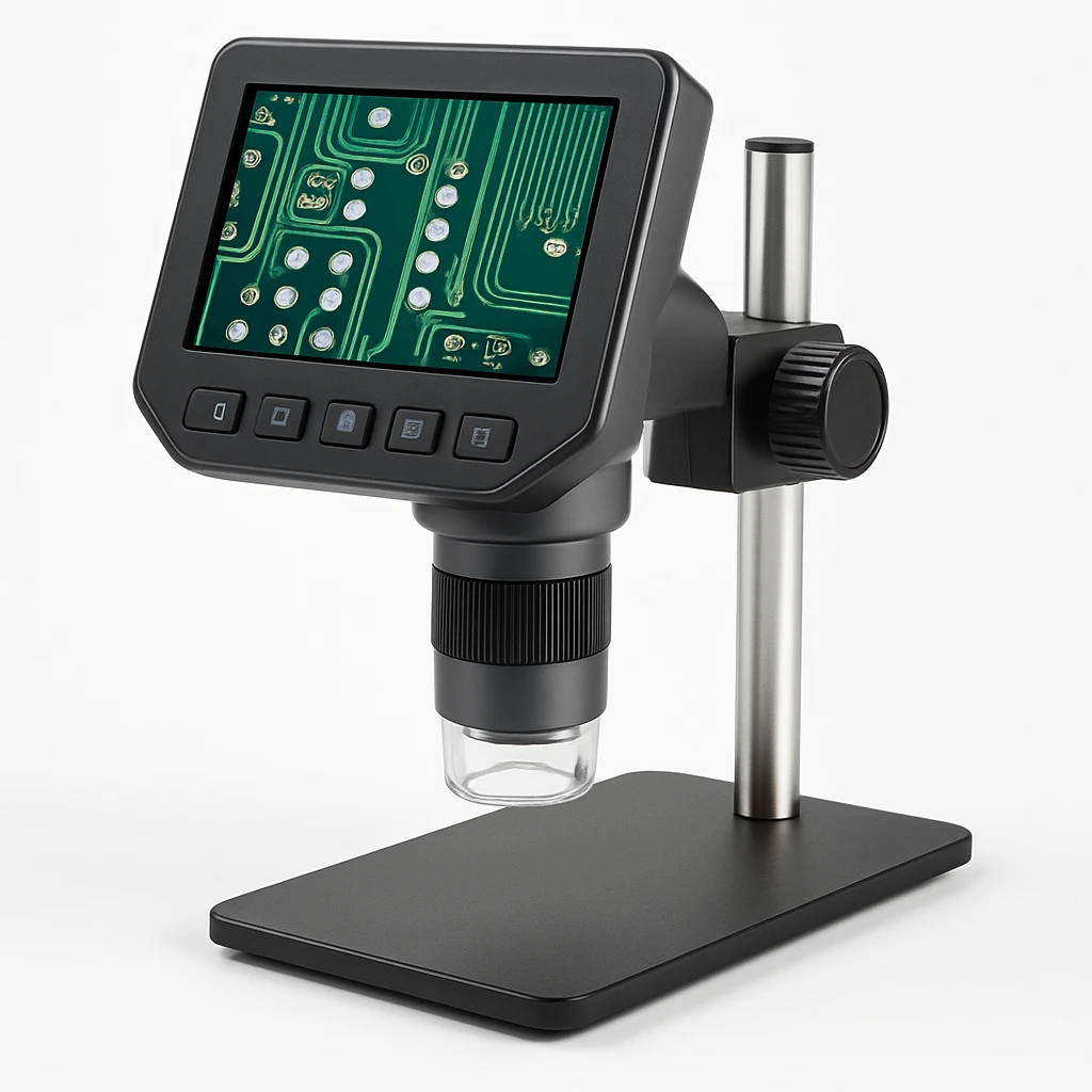
After this theme, we recommend you look for a digital microscope for PCB inspection.
This tool helps you identify cracked solder joints, damaged LCD ribbon connections, and tiny PCB faults with high magnification and clarity. A quality microscope makes diagnosing and repairing instrument clusters, ECUs, and modules significantly easier, safer, and more precise.

Step 9: Check Your Knowledge